NiTi Light (1/2)
This post is mostly a technical documentation of a project I have done a few years ago, and have never been documented before. The reason for doing a write-up now is so I can have a step back and see where I am today, compared to a few years ago. Also, it might be interesting to others. I hope my wife, which designed the lampshade, will someday do a write-up concerning her design decisions.
The post concerns the first project I did which involved an embedded microcontroller. As such, it was both my first foray into programming and electronics, since about seventh grade or so (about 20 years gap). It was also done in a rush, and quite a few compromises were done along the way - some because of necessity, some because of not knowing any better.
 NiTi Light blooming
About three years ago, my wife was working on her graduation project for industrial design studies, while I was going thru the sixth semester of plastic engineering. Her concept for the project was of a smart material lamp shade, using material change to infuse the object with transformation. After a long process of design exploration and experimentation, eventually my wife settled on a Nickel-Titanium (NiTi) alloy called NiTinol, which is remarkable as a shape-memory alloy. This means it can be set to a certain shape, to which it can “come back” after being deformed, and that effect is achieved through heating the NiTi alloy.
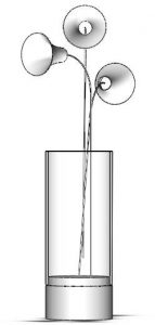
After settling on a material to work around, my wife than decided to construct a lamp, which eventually turned out to be a mock vase with LED-lit flowers. She also decided to use NiTinol in the form of wires. Those decisions made heating the NiTi wires quite a simple engineering problem: if the wire’s diameter, length, and resistance is known, it could be heated through resistive heating.
The electrical side was done in a bit of a rush, since the submission date was only a week after my exams were over. We decided to begin experimenting with the samples of Nitinol wire Aya had already purchased beforehand. The wire we had on hand was 0.5 mm diameter, 70°C phase change temperature. Aya’s design vision called for approximately 20 cm length of wire, with flower-like lampshades covering an LED module, set vertically in a clear plastic tube imitating a vase. In order to determine the power needed to raise the temperature of the Nitinol wire, we first needed to gain some understanding on the material properties.
 NiTi light CAD mockup
A quick look at Wikipedia and some MatWeb gave me enough data to calculate the energy required to raise the temperature of the length of Nitinol wire by 45°C (ΔT = [phase change T] - [room T, approximated as 25°C]).
d=0.05 cm; l= 20 cm; ρ = 6.45 g/cc; C = 0.32 J/(g * K); ΔT = 45°C Erequired = ρ * π (d^2 /4) * C * ΔT * l = 3.65 J = 3.65 W * sec \
Now, since the LED modules that were available to us at the time required 12.6 V, and P=I*V, I calculated the required current to get the desired temperature change, which will happen during 3 seconds:
I =3.65 / (12.6 * 3) = 0.13 A
As I found out later, this is a very simplistic calculation, and even taking a 9X margin of error did not produce satisfying results (I chose a 3 A transformer, which still did not get the 3 wires hot enough when used together). The calculation is simplistic in three significant ways: \
- This calculation does not take into account heat loss to the environment.
- The calculation does not take into account losses due to sub-par electrical connections (I will get to that in a bit).
- This calculation really should have been differential.
As it is, the calculation simply states that in an isolated environment a current of 130 mA is required to raise the temperature of the NiTi wire by 45°C, as it is seen by the viewer on the onset of the temperature gradient.
Since I did not know any better at the time, I decided we were good to go, and went ahead with figuring out what was needed electrically to control the heating. A friend got me his old Arduino diecimilla, Which is an older design of the Arduino development platform, and a predecessor to the most basic, standard offering of today’s Uno. The board is based on an ATmega168 microcontroller, runs on 5 V, and enough inputs and outputs for controlling the heating of three NiTi wires, light up some LEDs, and read the temperature of the wires for some measure of control. But, I guess I’m getting ahead of myself. Basically, I told my friend about the project, and he thought I might be able to pull off what my wife wanted from this board. I actually have never heard of Arduinos before approaching this project, and had limited experience in programming. I also had very little knowledge in electronics, mostly soldering kits and guitar parts.
Reading through some examples I figured I would need a N-channel MOSFET, connected to the Nitinol wire’s ground as sort of a “tap”, while the input will be connected straight to the 12.6 V bus. This way, I could control the current flowing through the wire using one of the Arduino pins. I also found that the correct topology for connecting the MOSFET to the Arduino would be to connect a diode between the gate and emitter. Since I wanted some level of control over the temperature change in the Nitinol wires, I decided to incorporate a LM35 temperature sensor, which could be read by the Arduino using the analog to digital converter (ADC).
I than went and got a few irf530 MOSFETs, some 1N4148 diodes, and complementary LM35’s from the local electronics shop. Since I had both limited knowledge and limited time on my hands, I got the parts that were available locally, for which I could get the guidance of the store owner. I then began testing heating one of the NiTi wires, using PWM to deliver current to the MOSFET gate. The Nitinol wire was pre-shaped to straighten as it’s “remembered” (austenite) state using the procedure provided by the vendor, Kellog’s Research Labs, and deformed by hand when in it’s malleable (martensite) state. I then used AC screw connections to connect the NiTi wire to short conductors, since the shape changing of the wire means it cannot be soldered securely. Essentially, heat - cool cycles means the soldered connection will be stressed regularly, and will eventually come apart.
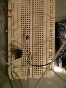
 MOSFET and diode on breadboard
As is visible from the shot I took of the process (above), the breadboard did not withstand the heat provided by this rudimentary circuit, and melted slightly around the MOSFET pins - though the experiment succeeded, and I decided to move forward.
This has been a long write-up, and I can see now I’m not even near the end I intended, so in my next post on the subject I will go on further into how I got the NiTi wires to heat up under a bang-bang control scheme, my Arduino stripboard shield, and what I think I should have done differently in retrospect.
